Specular Light Tutorial
Per Vertex Shader
Introduction
This article discusses the vertex and fragment shaders for the Specular Light: Plastic Ball, example. The fragment shader provides most of the functionality for the Specular Light: Plastic Ball example. The Capsule: Fragment Shader and Capsule: Vertex Shader examples, clearly demonstrate the difference between vertex and fragment shader processing. Yet all three examples follow the same pattern.
This tutorial explains the steps which generate specular lighting. This article briefly discusses the trade off between processing in the vertex shader, versus the fragment shader.
Seven Thunder Software didn't create the algorithm for the shaders presented here. Light algorithms are based on observations recorded as far back as 10 AD, with detail provided by others along the way.
Tradeoff Between Speed and Detail
Vertex shaders usually run less often than fragment shaders. Processing in the vertex shader should provide slightly more speed. However vertex shaders often produce less detail than fragment shaders. The Specular Light: Plastic Ball example processes lighting in the vertex shader. The Capsule: Fragment Shader and Capsule: Vertex Shader examples appear nearly identical except for detail.
More complex models processed in the fragment shader usually show more detail than models processed in the vertex shader. For example compare the capsule with lighting processed in the vertex shader to the capsule with lighting processed in the fragment shader, below.
Vertex Versus Fragment Shader Processing
The first capsule's lighting was processed primarily in the fragment shader. The second capsule's lighting was processed primarily in the vertex shader. Notice the difference in detail. The fragment shader processed capsule renders much more detail than the vertex shader processed capsule.
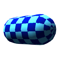
Fragment Shader Processing
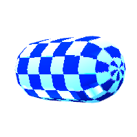
Vertex Shader Processing
Fragment shader processing code and vertex shader processing code are nearly identical, for the specular light examples. Most of the code simply moves to the fragment shader for fragment shader processing, or vertex shader for vertex shader processing. In other words, both shaders use the same steps to prepare rendering with light. Vertex shader processing accomplishes more in the vertex shader. Fragment shader processing accomplishes more in the fragment shader.
With vertex shader processing, the vertex shader calculates values
for the varying, v_lightweighting.
Vector v_lightweighting represents the amount of light to apply per fragment.
The fragment shader receives the value of v_lightweighting,
after interpolation by the GPU. Then the fragment shader modifies the
fragment color by the value in v_lightweighting.
With fragment shader processing, the fragment shader calculates
the value of vec3 v_lightweighting.
Continue reading for more details regarding vertex and fragment shader processing.
Model and Normal Matrices
The model matrix represents rotation and translation for cube vertices in the example projects. The normal matrix represents relative rotation and translation for normals associated with vertices in the cube.
The JavaScript for this example uploads an attribute with normal coordinates per vertex. Each frame of animation uploads a normal matrix. The normal matrix is a 3 x 3 matrix derived from the inverted and transposed model matrix.
That's a complicated way of saying the normal matrix represents a reduced model matrix. The 3 x 3 normal matrix contains the first three entries of the first three rows of the 4 x 4 model matrix.
The following two listings show a sample 4 x 4 model matrix, followed by the transposed and inverted 3 x 3 normal matrix.
Model Matrix
0.993,0.095,-0.06,0
0,0.528,0.849,0
0.112,-0.844,0.524,0
0,4.246,-7.641,1
Normal Matrix
0.993,0.095,-0.06
-0.001,0.528,0.849
0.112,-0.844,0.524
Vertex Shader
Varyings
The vertex shader sends
two varyings out for use
within the fragment shader.
Varying v_tex_coord0
simply receives texel
coordinates from
attribute a_tex_coord0.
Varying v_lightweighting
is the focus of this tutorial.
The vertex shader
assigns a value to v_lightweighting
representing the amount of light color to
apply for each vertex.
varying vec3 v_lightweighting;
varying vec2 v_tex_coord0;
Attributes
Attribute input to the vertex shader
include vec4
attributes for vertex coordinates,
associated vec3 normal coordinates,
as well as texel attributes. The texel attributes
are simply passed through a varying to
the fragment shader.
The following listing includes attribute
declarations for vertex coordinates,
normals and texels.
attribute vec4 a_position;
attribute vec3 a_normal;
attribute vec2 a_tex_coord0;
Constants
Constants within the vertex shader
include a vec3 representing ambient
light,
a vec3 representing
the light vector,
and a vec3 representing
the light color.
The following listing
shows the constant declarations.
const vec3 c_ambient = vec3(
 0.2,
 0.2,
 0.2
);

const vec3 c_light_location = vec3(
 -0.5,
 -0.5,
 1.0
);

const vec3 c_light_color = vec3(
 0.8,
 0.8,
 0.8
);
Uniforms
Uniform input to the vertex shader
include a 4 x 4 model view matrix um4_matrix,
3 x 3 normal matrix um3_nmatrix,
and a perspective projection
matrix um4_pmatrix.
The model view matrix
mat4 um4_matrix
represents rotation and translation
per frame.
The normal matrix
mat3 um3_nmatrix
also represents
rotation and translation per frame.
However multiply the 3 x 3 normal matrix
with a vec3 normal
and the 4 x 4 model view matrix with
vec4 vertex coordinates.
Determine the location of the current vertex modified by translation and rotation. The following line multiplies the model view matrix with the vertex coordinate.
vec4 v4_model_position = um4_matrix * a_position;
Determine the direction of the normal modified by translation and rotation. The following line multiplies the normal matrix with the normal attribute.
vec3 v3_normal = um3_nmatrix * a_normal;
Vectors
A GLSL vec3
represents three floating point values.
Developers can use vec3
in a number of ways.
For example shaders might
access the values of a vec3
as vertex coordinates with X,Y,Z values,
color channels with R,G,B values, or as a
vector.
A vector is a signed
displacement.
Vectors represent
direction and magnitude or length.
For example a vec3
with the following three values 1.0,3.0,2.0,
represent a displacement of one unit
on the X axis, three units on the Y axis,
and two units on the Z axis.
Apply the Pythagorean theorem to determine the magnitude.
The vector symbol is a line with an arrow at one end.
Vectors point in specific directions.
The arrow represents the direction of the vector.
First the vertex shader declares a vec4
which represents the transformed position
of the current vertex.
This article previously displayed the following line which assigns
the rotated or translated vertex coordinate
to vec4 v4_model_position.
The shader needs v4_model_position
for the next step.
vec4 v4_model_position = um4_matrix * a_position;
Second
the vertex shader calculates
vector v3_subtraction_vector
as the difference between the transformed vertex vector
and the constant light direction vector.
The shader
subtracts transformed vertex coordinates
from the light direction
vector.
Subtract
v4_model_position from c_direction_light.
vec3 v3_subtraction_vector = normalize(
 c_direction_light - v4_model_position.xyz
);
Imagine c_light_direction
and v4_model_position
touch at some point and form two edges of a triangle.
Vector v3_subtraction_vector
forms a triangle
of three edges.
Now the shader has a vector
which represents the difference
between the current vertex position
and the angle of the light.
In other words the vector describes the relationship
between the vertex and the light.
The built-in function
normalize() is applied
to the result.
The normalize() function
returns a vector with magnitude of one.
A vector with magnitude or length
of one is called a unit vector.
The direction of the normalized
vector remains the same.
Now find the relationship
between the normal and v3_subtraction_vector.
Use the dot product to determine
how much light to apply to this fragment.
Dot Product
Third take the dot product
of the transformed normal
and the subtraction vector
v3_subtraction_vector.
The dot product indicates the
amount of similarity between
the normal and the subtraction vector.
With two unit vectors dot product returns values between negative one and positive one. If the dot product returns zero, then two vectors are perpendicular. If the dot product returns a value greater than zero, the two vectors point about the same direction. Values greater than zero indicate an acute angle. A dot product of one indicates two vectors are parallel. Values less than zero indicate an obtuse angle.
The vertex shader uses dot product to determine how much light color the fragment shader will mix with the sampler color. If the dot product returns zero, the vectors are perpendicular, apply zero brightness from the light color to the current fragment. If the dot product returns a value greater than zero, the two vectors point about the same direction. Multiply the value returned by the dot product and the light color, then apply that value to the fragment color.
The final result provides gradual shading across each surface, taking into account the vertex position, normal and light direction. The following listing demonstrates taking the dot product between the transformed normal and the subtraction vector.
dot(
 v3_normal,
 v3_subtraction_vector
)
Call the built-in function
max()
to return only non negative numbers.
Assign the result to the floating
point number
f_light_weighting.
float f_light_weighting = max(
 dot(
  normalize(v3_normal),
  v3_subtraction_vector
 ),
 0.0
);
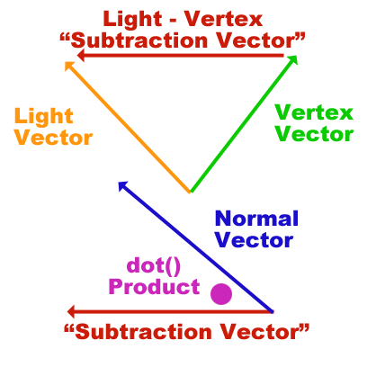
Light Diagram
Two vector operations determine the amount of light color to apply to
a fragment. Subtract the vertex vector from the light vector.
The result is labeled Subtraction Vector
in the following
diagram.
Call the dot() product function, to find the
amount of similarity between the Subtraction Vector
and the normal vector.
If the angle between vectors is acute, then apply light color.
The more similar the vectors are, the more light color applies for this vertex.
If the vectors are perpendicular or obtuse, then apply zero light color.
Last the vertex shader determines the amount
of light color to send out for
the fragment shader.
Multiply the light color
by the result of the dot product.
Add in the ambient light.
The sum equals the amount
of light to apply for this vertex.
Assign the result to
the varying v_lightweighting.
The GPU interpolates values
then sends them on to the fragment
shader through the varying
with the same name; v_lightweighting.
v_lightweighting =
 c_ambient +
 c_light_color * f_light_weighting;
The vertex shader also
multiplies the modified vertex coordinate
by the perspective projection matrix.
Last the built in variable
gl_Position
receives the modified vertex coordinate.
The listing for the entire vertex shader follows.
attribute vec4 a_position;
attribute vec2 a_tex_coord0;
varying vec2 v_tex_coord0;

attribute vec4 a_normal;

// Translated or
// rotated normal matrix.
uniform mat3 um3_nmatrix;

 // Translated or
 // rotated  model matrix:
 uniform mat4 um4_matrix;

// PP matrix.
uniform mat4 um4_pmatrix;

const vec3 c_ambient = vec3(
 0.2,
 0.2,
 0.2
);

const vec3 c_light_location = vec3(
 -0.5,
 -0.5,
 1.0
);

const vec3 c_light_color = vec3(
 0.8,
 0.8,
 0.8
);

varying vec3 v_lightweighting;

void main(void) {
 // The position of the
 // vertex after rotation and translation.
 vec4 v4_model_position = um4_matrix * a_position;


 // Determine the direction of the normal
 // relative to the current
 // rotation and translation.
 vec3 v3_normal = um3_nmatrix * a_normal;

 // Find the vector
 // which represents the
 // difference between
 // the light vector
 // and the position
 // of the current vertex.

 // The vector from
 // the vertex coordinate
 // to the light direction.
 vec3 v3_subtraction_vector = normalize
 (
  c_light_location - v4_model_position.xyz
 );

 // The amount of light.
 // Dot product of the normal
 // direction and light direction.
 // max() restricts result
 // to non negative numbers.
 float f_light_weighting = max(
  dot(
   v3_normal,
   v3_subtraction_vector
  ),
  0.0
 );

 // Varying output.
 v_tex_coord0 = a_tex_coord0;

 // Assign the amount
 // of light to apply
 // to this vertex,
 // to the varying:
 v_lightweighting =
  c_ambient +
  c_light_color * f_light_weighting;

 gl_Position = um4_pmatrix * v4_model_position;
}
Fragment Shader
Very little happens in the fragment shader compared to the vertex shader
Varying output from the
vertex shader become input
for the fragment shader,
after the GPU interpolates values.
The fragment shader receives
the vec2 varying
v_tex_coord0
as texel coordinates to sample the
texture.
The fragment shader receives
the vec3 varying
v_lightweighting
which represents the amount
of light to apply to this fragment.
The fragment shader samples
a texture.
The fragment shader multiplies the RGB values
of the sample, by the varying v_lightweighting.
Maintain the sample's original alpha value.
gl_FragColor = vec4(
 color0.rgb * v_lightweighting,
 color0.a
);
The entire fragment shader source code follows.
precision mediump float;

// Texel.
varying vec2 v_tex_coord0;

// The amount of
// light to apply
// to this fragment.
varying vec3 v_lightweighting;

uniform sampler2D u_sampler0;

void main(void) {

// Sample the texture.
vec4 v4_color0 = texture2D(
 u_sampler0,
 v_tex_coord0
);

// Multiply the
// sample color's RGB
// values by the amount
// of light to apply.
gl_FragColor = vec4(
 v4_color0.rgb * v_lightweighting,
 v4_color0.a
);
}
Summary
This article discussed the vertex and fragment shaders for the Specular Light:Plastic Ball example. The vertex shader provides most of the functionality for the Specular Light:Plastic Ball example. The Capsule: Fragment Shader and Capsule: Vertex Shader examples process lighting primarily in the fragment shader. Yet all three examples follow the same pattern.
This tutorial explained the steps which generate specular lighting. This article briefly discussed the trade off between processing in the vertex shader, versus the fragment shader.