WebGL Points Tutorial
Swipe From the Center Outward
Overview
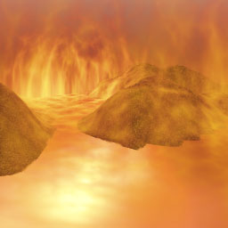
This tutorial covers four techniques to use with WebGL points. The WebGL Particle Explosion project combines concepts used in three WebGL point examples including WebGL Square Points, WebGL Face Mapped Points and WebGL Simple Round Points. First points react to user interaction. Second points are mapped with a texture. Third shaders draw circular points. Fourth the WebGL blend function causes overlapping points to appear brighter. Brighter overlapping points create the illusion of more heat toward the center of the explosion when sprites draw over each other.
JavaScript Constructor
The JavaScript constructor creates a reference of
type GLPointsExplode defined
within JavaScript file GLPointsExplode.js
.
First this tutorial covers JavaScript which loads a square flat plane defined with sixteen vertices. Each vertex represents a point. Create three entities which will access the same same set of vertices, with different matrices for rotation and translation. You may download the JavaScript Model which is used to create a square plane with sixteen vertices.
The following listing initializes three square planes. The matrices are offset along the X, Y, or Z axes.
var shapes = new PlanePoints();

var aIm = new Array();

// Initialize the
// entity with a texture.
var e =  new GLEntity(
 s,
 0
);

e.nOffset = Number(
 shapes.aOffset[0]
);

e.nCount = Number(
 shapes.aCount[0]
);

e.matrix[14] = -2.5;

aIm.push(e);

e =  new GLEntity(
 null,1
);

e.nOffset = Number(
 shapes.aOffset[0]
);

e.nCount = Number(
 shapes.aCount[0]
);

e.matrix[14] = -5;
e.matrix[12] = -0.2;
e.matrix[13] = -0.2;

aIm.push(e);

e =  new GLEntity(
 null,
 2
);

e.nOffset = Number(
 shapes.aOffset[0]
);

e.nCount = Number(
 shapes.aCount[0]
);

e.matrix[14] = -5;
e.matrix[12] = 0.2;
e.matrix[13] = 0.2;
aIm.push(e);
Last the constructor creates a controller, GLControl reference.
The controller initializes a vertex buffer object with the
vertices and element array index declared in
the JavaScript Model.
For more details regarding the exploding points example
see the
JavaScript Constructor.
var controller = new GLControl
(
 shapes.aVertices,
 shapes.aIndices,
 aIm,
 this
);
JavaScript Initialization
Before displaying the first frame JavaScript prepares some variables for rendering. For the explosion example set the clear color to black.
gl.clearColor(
 0.0,
 0.0,
 0.0,
 1.0
);
The plane includes vertices only.
Neither texels nor vertex colors are needed with face
mapped points.
The following call to
vertexAttribPointer()
describes the arrangement of
vertices within the vertex buffer object.
Three vertices follow each other sequentially
with no gaps in between.
gl.vertexAttribPointer
(
 controller.aPosition,
 3,
 gl.FLOAT,
 gl.FALSE,
 0,
 0
);
Save the location of three uniforms named
uf_x, uf_y, and uf_pointsize.
Uniforms uf_x and uf_y
represent the user's current X and Y touch or mouse
point on the canvas.
Uniform uf_pointsize adjusts the
size of WebGL points before performing a draw operation.
glDemo.ufX = gl.getUniformLocation(
 controller.program,
 "uf_x"
);

// Uniform to modify Y
// coordinates by time.
glDemo.ufY = gl.getUniformLocation(
 controller.program,
 "uf_y"
);

// Change size of
// points by time.
glDemo.ufPointSize = gl.getUniformLocation(
 controller.program,
 "uf_pointsize"
);
Prepare to blend points when they overlap.
WebGL methods enable(gl.BLEND)
and
blendFunc(...)
modify color channels when points
draw over each other.
The destination gl.ONE_MINUS_CONSTANT_COLOR selection,
causes the center of the explosion to appear brighter.
Color channels are added together when areas overlap.
The following listing demonstrates preparing
blendFunc() to modify WebGL rendering
output for
the WebGL Particle Explosion
example.
gl.enable(
 gl.BLEND
);

gl.blendFunc(
 gl.ONE,
 gl.ONE_MINUS_CONSTANT_COLOR
);
See the entire JavaScript initialization source code.
JavaScript render()
The render() method
accesses properties nX, nY,
and nMiddle to calculate
the amount of rotation for each
plane's matrix.
Properties nX and nY
represent the user's current touch or
mouse coordinates over the canvas.
Property nMiddle is just the middle
of the canvas.
Variable glDemo is a
reference to this project's class
named GLPointsExplode.
The following few lines demonstrate
preparing X and Y coordinates for
upload to the vertex shader
using properties nX, nY, and
nMiddle.
Before upload to the GPU coordinates nX and nY
need conversion from canvas coordinates to GPU coordinates.
Canvas coordinates are in the range {0..canvas.width}.
GPU coordinates are in the range {-1.0..0..+1.0}.
var glDemo = controller.glDemo;

var aEntities = controller.aEntities;


// Normalize the current X,Y touch point.
// Range [-1.0...+1.0]

var nX = Number(
 glDemo.nX - glDemo.nMiddle
);

var nXA = Math.abs(nX);

nX /= glDemo.nMiddle;


var nY = Number(
 glDemo.nY - glDemo.nMiddle
);

var nYA = Math.abs(nY);

nY /= glDemo.nMiddle;

var nAvg = (nXA+nYA)/glDemo.nMiddle;

var nPointSize = (1 - nAvg) * 128;
Calculate the point size based on the user's touch position on the canvas using converted GPU coordinates.
var nAvg = (nXA+nYA)/glDemo.nMiddle;

var nPointSize = (1 - nAvg) * 128;
Upload the X, Y, and point size values to the vertex shader.
gl.uniform1f
(
 glDemo.ufX,
 nX
);

gl.uniform1f
(
 glDemo.ufY,
 nY
);

gl.uniform1f
(
 glDemo.ufPointSize,
 nPointSize
);
Last iterate over the list of entities. For each entity rotate the matrix, upload the matrix to the shader, then draw the matrix.
Three sets of points are drawn with different rotations. Mouse or touch interaction offsets the size and coordinates of points. For more exciting realistic explosions apply random numbers to point coordinates.
mat4.set(
 e.matrix,
 matrix
);

if (i % 2 == 1){
 mat4.rotate(
 matrix,
 controller.nRad,
 [0,0,1]
);

}
else {
 mat4.rotate(
  matrix,
  -controller.nRad,
  [0,0,1]
 );
}

gl.uniformMatrix4fv
(
 controller.uMatrixTransform,
 false,
 new Float32Array
 (
  matrix
 )
);
The following call to the WebGL method drawElements(),
draws a set of points.
Number e.nCount contains the number of points to draw.
Number e.nOffset indicates where, to begin
drawing, within the vertex buffer object.
Notice the first parameter is gl.POINTS.
Each vertex represents one point.
WebGL examples often pass gl.TRIANGLES as the
first parameter, which draws triangles.
WebGL drawElements()
gl.drawElements
(
 gl.POINTS,
 e.nCount,
 gl.UNSIGNED_SHORT,
 e.nOffset
);
See the entire rendering source code.
Vertex Shader
The vertex shader copies the
current vertex coordinates from attribute a_position to local vector pos.
Next the shader multiplies the current vertex X and Y coordinates by
uniforms uf_x and uf_y.
The previous section titled JavaScript render()
,
demonstrated uploading
values to uniforms uf_x and uf_y
during rendering.
vec4 pos = a_position;
pos.x *= uf_x;
pos.y *= uf_y;
Assign the product of the perspective matrix
um4_pmatrix, the transformation
matrix um4_matrix,
and the modified vertex coordinates,
to built in vector gl_Position.
gl_Position =  um4_pmatrix *
 um4_matrix *
 pos;
Last assign the value from
uniform uf_pointsize
to the built in variable
gl_PointSize.
Modifying gl_PointSize
allows different particles
to
render at different sizes.
However not all browsers support it.
See the entire vertex shader
for more details.
Fragment Shader
The fragment shader first tests to determine if the fragment's coordinate is within the area defined by a circle.
The distance() function
returns a floating point value
representing the distance between
two values.
The following function call tests
the distance from the center of the
point's texture to the current
coordinate on the point.
float f_center_distance = distance(
 gl_PointCoord,
 vec2(0.5,0.5)
);
If the distance is greater than 0.5
just return. Don't render this fragment.
The corners of a square point would return
a value of 0.707. The following
code avoids drawing the corners of the square,
eventually rendering a round area for each point.
if ( f_center_distance >= 0.5 ) {
 discard;
}
Next sample the texture at the current point coordinate.
vec4 color0 = texture2D(
 u_sampler0,
 gl_PointCoord
);
Last multiply the sampled color
by constant cf_dark.
See the entire fragment shader for more details.
Tips
Some older Android Chrome and Firefox browsers lock up with texture mapped points. Additionally older Microsoft browsers haven't implemented point size modifications. Points display as one pixel only. However Microsoft Edge does display texture mapped points at various point sizes.
Summary
This tutorial covered four techniques to use with WebGL points. The WebGL Particle Explosion project combines concepts used in three WebGL point examples including WebGL Square Points, WebGL Face Mapped Points and WebGL Simple Round Points. First points react to user interaction. Second points are mapped with a texture. Third shaders draw circular points. Fourth the WebGL blend function causes overlapping points to appear brighter. Brighter overlapping points create the illusion of more heat toward the center of the explosion when sprites draw over each other.
